


The MediaTek MT6158 is a 40nm CMOS single-chip multiband RF transceiver. It is fully compliant with the 3GPP2 specification of CDMA20001xRTT/EV-DO. Supports all critical global band assignments as well as diversity reception. The RF transceiver function is fully integrated. This article provides a brief introduction to RF macros in MT6158.
MT6158 Application Diagram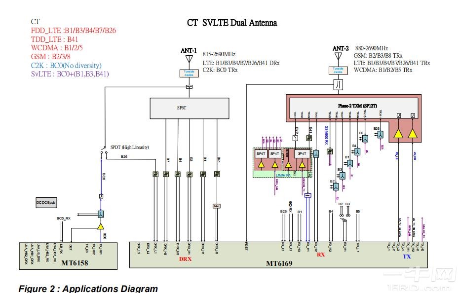
1. Single-mode RF solution (CDMA2000)
1xRTT Rel.0 and EVDO versions. A (1xRTT: 153.6kbps download rate, DO: 3.1/1.8Mbps download/upload)
C.S0011D(1xRTT)+C.S0033C(EVDO)
Operating frequency band: BC0, BC1, BC4, BC6, BC10, BC14, BC15
1LB+2HB at the same time
Supports 1xRTT and EVDO diversity
Simultaneous Hybrid Dual Receiver (SHDR) support
2xBSI, 1 dedicated to TX power control
2. Direct conversion transmitter: the transmitter does not need an external SAW filter; Dedicated power detection circuitry for power control in a specific power range
3. Direct conversion receiver: The receiver does not need an external SAW filter
4. 26MHz internal DCXO: ultra-low power consumption 32KHz mode
5. Support RF calibration function of key Rx and Tx specifications (low feed, DC offset)
6. Temperature measurement subsystem
7. Integrated power detector and measurement receiver (high dynamic range with fast true RMS detector)
Receiver specifications
The receiver design supports diversity and consists of two sets of receiver front-end modules and two sets of synthesizer modules. Each receiver path supports two high bands and one low band. Two separate synthesizers are used for the LO generation mode required for receiver diversity and SHDR. All LNAs have balanced inputs and are fully integrated. The quadrature LO signal is generated by a divide-by-2 for high-frequency (HB) lnas and a divide-by-4 divider for low-frequency (LB) lna. The RF signal is downconverted through a high/low-band quadrature direct downconversion mixer. An analog baseband filter is a low-pass filter with programmable transmission and gain control. In addition, it includes an RC calibration circuit and a DC offset cancellation circuit (DCOC). The low-pass filter is a third-order Cheybechev I. The receiver's power on/off sequence, LNA/band selection, total receiver gain including LNAs, mixer and analog baseband, and DCOC timing are controlled by digital circuitry. The timing and control of these calibration schemes are also controlled by L1 software and digital circuitry.
Other
What is HBM (High Bandwidth Memory)?
2024.09.05
What is Antenna Tuner IC?
2024.09.20
What’s the Difference between LPDDR and DDR?
2024.09.25
Snapdragon 888 5G Mobile Platform
2024.09.26
What is WiFi 6E?
2024.09.26
What is Bluetooth Audio SoC?
2024.09.26
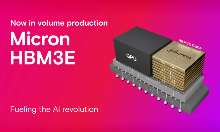
What's HBM3E (High Bandwidth Memory 3)?
2024.09.26

What is an Audio Codec?
2024.10.09